BPS12_a
The BPS12 is a wi-fi link that connects to the BP2. It is only compatible with the BP2 and will not fit on the BP1 or any Arduino. It has an on board power supply that will power the wi-fi module and the BP2, thus an independent system can be created.
Assembly
The BP12 12 comes ready assembled but there is some soldering to do to connect it to the BP2.
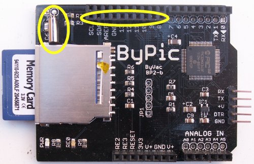
1) A 10 way connector is soldered to the inner row of sockets as shown
2) Optionally the RTC low frequency crystal can be soldered in place at JP3. This will enable the BP2 to keep track of real time once the clock is set. This is optional because this function may not be needed. There is no battery back up and so the clock will need resetting at each power up. If the device is connected to the internet then the time can be obtained from there.
The BPS12 will now simply connect to the BP2 and the supply power to theBP2.
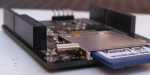
Make sure that if fitting the crystal it does not short out the capacitors underneath. It can be mounted just above as shown.
Serial Connection
The normal serial connections should be be used, however the USB cannot supply sufficient power to operate the wi-fi module and so the BPS12 power supply should be used to power both.
WARNING
When supplying power form the BPS12 do not also use power from the USB. Leave the +V pin disconnected.
<< picture of USB to Serial Connected >>
Leave the middle pin disconnected.
Initially leave the S-LINK jumpers open circuit (removed) for now. This will enable communication via a USB to Serial as normal.
Power Supply
Any voltage source from 7V to 35V, AC or DC will do. This can be from a battery, wall wart power supply or transformer. If this is a DC supply then polarity does not matter, connect to the screw terminals either way round.
The BPS12 uses an adjustable supply that has been set for 5V, under no circumstances should the voltage be adjusted, a voltage greater then 5.3V will damage the wi-fi module.
Description
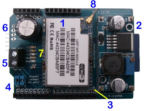
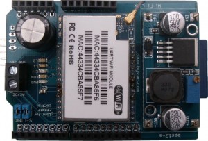
[1] Wi-Fi Module
[2] Voltage regulator
[3] Inner connector
[4] Serial link to UART 2
[5] Power input
[6] Auxiliary power outputs
[7] LED indicators
[8] Antenna connection
[1] The WiFi module is a HI-LINK RM04 that does the work of communications from a network level to a serial level. Ti will work without an antenna but only for relatively short distances. The module requires 5V at about 100 to 200mA and so will not work very well of a USB power supply. Id does output 3V3 at about 100mA and this can be used for other purposes. The output from the module is taken to [6]. The module is capable of output to RJ45 type sockets for a wired LAN but for this application that is not used.
[2] The power regulator is based on an LM2596 and is capable of about 1A to 3A, although at 3A it will need a better heat sink. The PCB is set to be adjustable and there is a screw for that purpose. It has been set to 5V and must not be adjusted as this will damage the Wi-Fi module.
[3] The inner connector is used to mate with the BP2 and as such the BP2 will require a connector fitting.
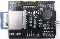
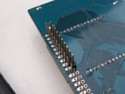
The 10 way socket is provided with the PBS12 and should be soldered to the inner row of pads as shown on the left picture. The right picture shows the underside of the PBS12 with the pins that mate with this socket.
10 Way inner Connector
SCL (inner) RF5(UART2 TX) Connected to the serial link jumper - GP3 (Rx2) on wifi module, pin 22
SDA (inner) RF4(UART2 RX) Connected to the serial link jumper - GP5 (TX2) on wifi module, pin 26
AREF (inner) RE1 Connected to the ES/RST pin used to set AT mode 1, pin 10
GND (inner) RF6 Connected to the Con LED
9 (inner) RB11 Connected to the Err LED
8 (inner) RB10 Connected to L1 LED
8 Way Digital Connector (outer)
2 (UART1 TX) Connected to wifi module RX pin 20
1 (UART1 RX) Connected to wifi module TX pin 21
8 Way power connector
RE2 (RE2) Connected to LED L2
[4] The module can be a wi-fi link to the UART 2 communication that is normally used on the BP2 5 pin connector. With the jumpers in place a socket can be established for main communication, more details of this can be found in the general description.
[5] The power input is a screw terminal that can accept both AC or DC and so polarity does not matter. Fro best results the voltage should be above 7V and should not exceed 35V. There is a rectifier under the wi-fi module that takes care of the conversion from AC to DC. The large capacitor will also help to prevent any interference from voltage spikes.
[6] There are three voltage outputs available for general use:
- +V This is the rectified and smoothed input voltage, ideal for powering high power devices. an example would be to feed the input [5] with a 12 ro 24V supply and then use +V to power a motor device.
- +5V This is the output from the voltage regulator [2] and should be set to 5V. It is good for up to 3A given a suitable input and a heat sink.
- +33 This is the 3.3V output from the wi-fi module. It is separate from the 3.3V regulator used on the BP2 and so should be okay to power external equipment up to about 100mA.
[7] All of the LED indicators except for the PWR LED are programmable using the ports as described in [3]. The pwr indicator is connected to the BP2 3.3V supply and so will indicate if the BP2 is connected and powered up.
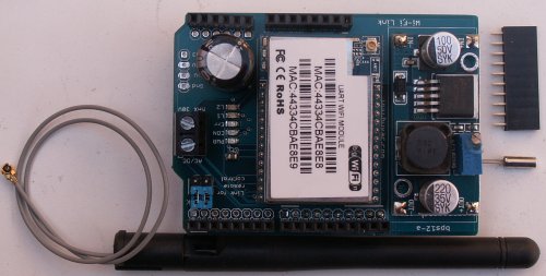
[8] An antenna is provided but the module will work without one for a limited range. The connector is standard ans so will take a variety of different kinds of antenna.
Circuit Diagram
Click on image to enlarge.