BV501
- Hardware
- Programming
- Screen & ATFlash Commands
- Getting Started
- Images
 ByPic Language Guide and documentation
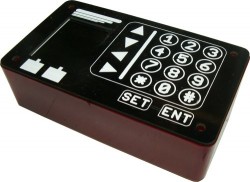
At the moment this is not available for sale.There is however an alternative product that is designed as a front panel and works with an I2C interface.
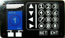
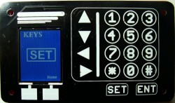
This is a ByPic processor with a 1.8" full colour screen and an assortment of touch buttons. It can form the basis of a front panel to control other devices.
The BV501 behind the front panel runs ByPic which is a simple scripting language so that the device can be programmed simply using text.
Applications for this could be: Central heating, Air Conditioning control, Automotive applications, Solar panel, Computer network control etc.
The device could also be programmed to act as an input / output device for another computer. This could be achieved via the serial or I2C interface.
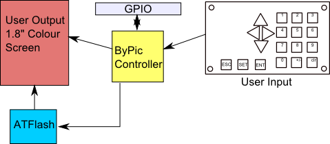
Block Diagram
User output is provided by a full colour screen with a resolution of 128 x 160 pixels. The ATflash can store user images and fonts. Input is provided by a touch panel. A program runs on the ByPic that will sense the keys being touched. The ByPic firmware is extended to manage the ATFlash and screen.
Hardware
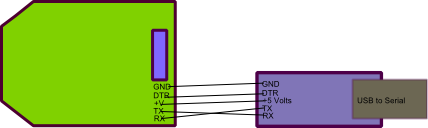
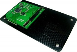
The BV501 is in two parts, the rear PCB that holds the processor and screen and the front PCB that is the user interface. They attach together by means of 10 solder pads and so custom front panels could be manufactured using PCB technology.
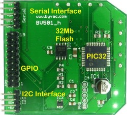
Serial Interface
This is connected to UART2 and is the main form of communication with the board. There is also a UART1 that can be used for any other general communication, this is accessed via the GPIO connector.
Programming is done via this interface by sending text to the device. This can be saved to the processors flash to become a stand alone application. Power is also supplied on one of these pins.
RX: This is an input and will receive signals from a USB to serial converter or similar. It must NOT be connected to a COM port directly (i.e. the 9 pin type)
TX: Is the output and should go to the RX of a USB to Serial converter or similar.
+5V: This can be up to 6V as the on board regulator will take the voltage down to 3.3V
DTR: If one is available this should be connected to the DTR on the USB to Serial converter. This is held high by an internal pull up resistor, bringing this line momentarily low will reset the device
GPIO
This has all of the rest of the i/o pins from the processor. Ten pins are used for the touch interface (see Front panel below).
|
Pin 19 |
Pin 17 |
Pin 15 |
Pin 13 |
Pin 11 |
Pin 9 |
Pin 7 |
Pin 5 |
Pin 3 |
Pin 1 |
|
GND |
GND |
RC4 |
RC3 |
RB13 (AN11) |
RB6 |
RB4 |
RA9 |
RC8 |
RC6 |
|
V+ [1] |
V+ [1] |
+3.3V[2] |
RC5 |
RB15 (AN9) |
RB7 |
RB5 |
RA10 |
RC9 |
RC7 |
|
Pin 20 |
Pin 18 |
Pin 16 |
Pin 14 |
Pin 12 |
Pin 10 |
Pin 8 |
Pin 6 |
Pin 4 |
Pin 2 |
NOTES [1] This is connected to the +5V pin on the serial and I2C interfaces and so can be an input, providing power or the board, or an output.
[2] This is the output from the on board regulator, this should be good for about 50mA or so depending on the ambient temperature.
I2C Interface
The I2C interface can either be a slave or master. It has built in 10k pull up resistors and is wholly controlled by software. A library is available for either master or slave. To use this interface the software needs to be installed first via the serial interface.
SCL: RB8
SDA: RB9
Power
Power is supplied to the board from either the serial, I2C or GPIO connectors. The board works at 3.3V and this is provided by the on board regulator. The maximum voltage the regulator can handle is 6V and so can be supplied via 4x1.5V cells for battery operation.
The following pins are all connected to each other:
Serial pin 3, I2C pin 4, GPIO pins 18 and 20
Serial Flash (ATFlash)
This a 32Mb serial flash device that uses SPI channel 1 on the processor. This channel also controls the display. This memory, referred to as ATFlash to distinguish it from the spare flash on the microprocessor, is for storing images and fonts. A simple filing system is used that works in conjunction with the ByPic commands and BvSerial.
There is room for 1000 (0-999) x 4096 Byte blocks.
The Front Panel
This is attached to the main processor board by 10 connections that provide a physical and electrical interface. Looking at the BV501 the top row has the following pin designations:
|
RC2 |
RC0 |
RB2 |
RB0 |
RA0 |
The vertical connector is:
|
GND |
|
RA0 |
|
RB1 |
|
RB3 |
|
RC1 |
These provide the row and column connections to the front panel. The CTMU built into the PIC32 uses the ADC function to detect which pad is being touched. If the board for any reason is not being used with the front panel then these pins are free to be used for anything else. In fact because the code to drive these is user controlled only a few pads may be needed thus freeing up some pins.
PIC32
The processor is a PIC32MX150F128D, this has 128K flash and 32K ram. A large proportion of the flash is taken with the ByPic operating system and screen drivers. However there is still sufficient room for complex programs. The actual spare flash is 17k. It is impossible to say just how much a particular program will use but the installed demo uses about 12k and there is a reasonable amount of redundant code in that.
If this is a limiting factor then there is planned an enhanced version that will use the PIC32MX370 (not available at the time of writing) which has 512k flash and 128k RAM
Some other features of this processor are:
- 40MHz clock rate
- 20uA low current mode (may not be achievable on this device)
- Audio features
- ADC 10 bit
- Charge Time Measurement Unit
- Comparators
- Timers (5)
- SPI, I2C, UART x 2
- Some pins are 5V tolerant
Circuit Diagram
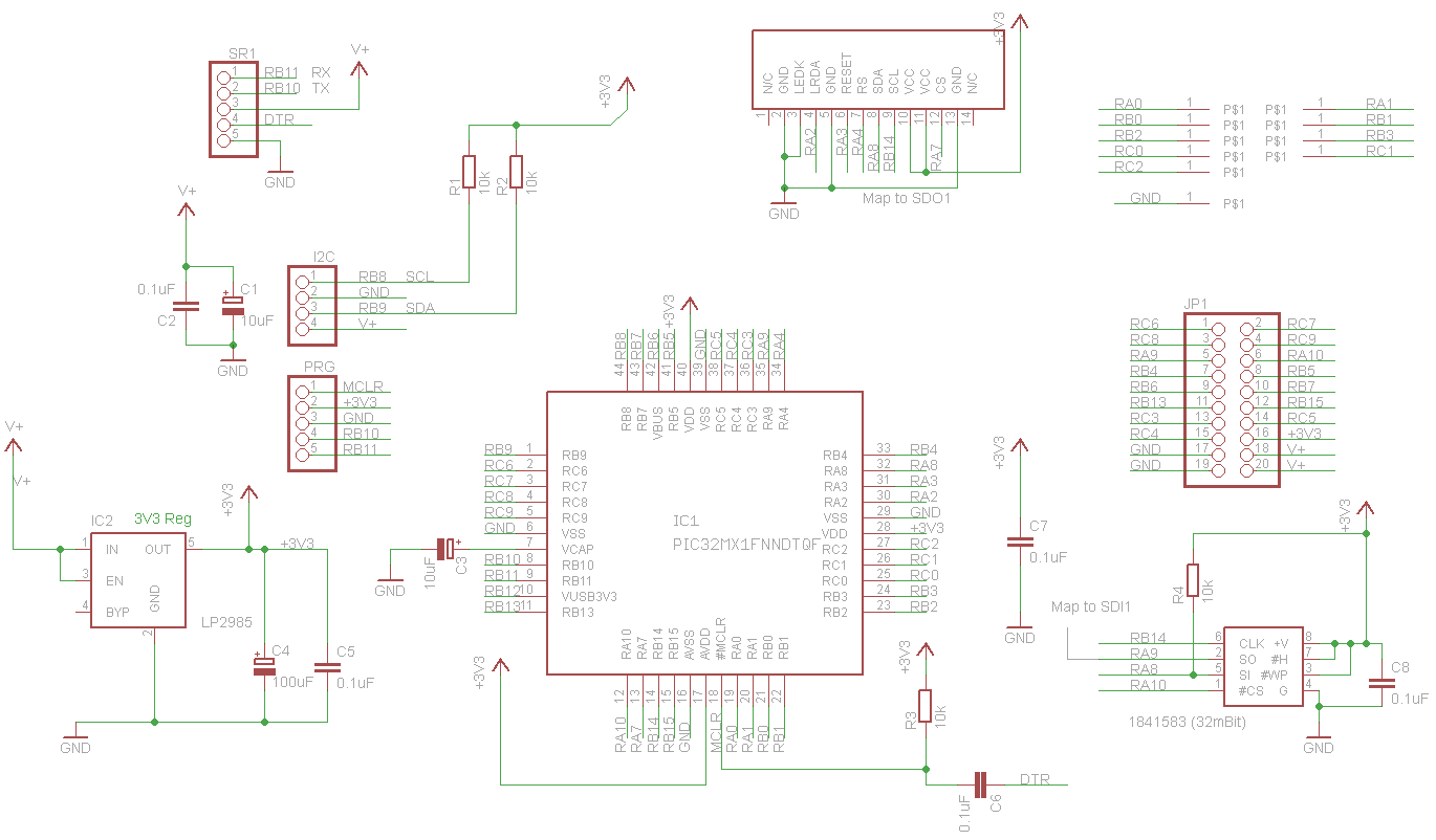
Click to enlarge
Programming
ByPic
The device has installed ByPic. This is permanently in flash and makes programming much easier. No programmer is required simply download the code using a serial connection, the code is written in text, this includes the libraries and so can be modified by the user as required.
Full details of the ByPic language is here: www.bypic.co.uk
Touch Interface Software
This uses the CTMU hardware built into the PIC32 and has proven very reliable especially when the pads are part of a PCB. To give the maximum flexibility the code to drive this is not part of the firmware but a user supplied library of ByPic code. This gives the user the opportunity to tailor the code to suit a particular need. The code to drive the touch panel is called " bv501touch_05.bas", 05 being the version. This should be downloaded into flash and then saved with flsave(""). Once in there, using the keypad is as simple as initialising it; the function keypad() will return a key code or 0.
The demo.bas gives an indication of how this works.
Images
Images are stored in the on board serial flash (atflash) and are used by calling their filename. To get the image on the flash the BvSerial command .upm is used followed by the file name - a GUI is available on the latest version 7 onwards.
An image must be a 24bit type .bmp file, this will usually have 32 or 64k colours. When the image is downloaded via BvSerial it is converted before saving to flash to a form that the BV501 can use.
The ByPic Commands for this are the same as that for the BV523, see the ByPic keyword list for 'screen'
Fonts
There are no built in fonts. The firmware will look on the atflash for a font called "default.bff" and use that.
Fonts are created by the user using CBFG.exe and then saved to the atflash using BvSerial with the .upm command. There is no need to do any conversion as BvSerial will do that.
Screen and Flash Commands
Most of the screen commands used for the BV523 will work on the BV501 however the following functions are particular to the BV501.
Special note about the ATFlash: The flash must be erased before write and the minimum number of bytes that can be erased at any one time is 1 block (4096 bytes). This has implications for storing random data bytes.
difont("filname") This will load a font from the atflash for current use. The font must exist on atflash and the full filename is used.
Example: difont("default.bff")
Once the font has been loaded then the normal text commands can be used e.g.
ditext(“text to display”)
diputs(x,y,colour,“string”)
diimage("image name",x,y) Places an image at the given x,y co-ordinates. The image must exist on atflash and the full filename given.
Example: diimage("my dog",0,0)
atlist() Lists all the file details that are on the atflash
atfind("filename") Designed for use programmatically this returns the following values:
-1 atflash full
-4 atflash some error
-10000 or greater, block where file exists, i.e. add 10000 to this for the actual block
+10000 the next free block when file does not exist, i.e. subtract 10000 to find out actual block number.
atread(buf,address,bytes) Reads into a buffer, from the address of the atflash the number of bytes. Note the address is blockNumber * 4096
Example: Read 20 bytes from block 50:
dim buf$[30]
atread(?buf$+4,50*4096,20)
dump(?buf$,0)
The first 4 bytes of a string are the size of the string and so its best to start at +4.
atwrite(buf,address,bytes) Writes bytes, see atread().
atdump(n) This is the equivalent to dump() but will dump the contents of atflash, if n < 999 then n will be a block number, if > 999 then it will be an address.
atload(block) This is used by BvSerial to load bytes into the atflash. It will write a block of data to the given block number. The data is sent via the com port with length first followed by the data, sending a length of 0 will terminate the transfer. For more information see def send_block(sp,data,dlen) in bvtools.py.
** This command would not normally be used by the user.
aterase(from,to) Erases a block of blocks of flash. The fromm and to are specified as blocks. Before writing the block must be erased first. The minimum that can be erased is one block.
Example: erase blocks 5 through 9 aterase(5,9)
ateraseall() Erases the entire flash, this can take 30 or more seconds.
atput(address,byte) Puts a single byte at a particular address, the byte at the address must be blank. This applies to all atwrite commands. The command will NOT erase before write.
x = atget(address) Gets a single byte from a particular address.
Getting Started
The complete BV501 (with front and back panels) comes with demonstration software. This consists of files stored in the ATFlash and also ByPic programs stored on the controller flash. To communicate with the BV501 requires a serial interface and power supply.
This is provided by a BV104 or similar device. The TX form the USB to Serial goes to the RX on the BV501 and the RX on the USB to Serial goes to the TX on the BV501. Communication is at a fixed Baud rate of 115200.
Any terminal emulator software can be used but BvSerial has some built in programs that enable uploading of programs and media so it is recommended that BvSerial be used. Details are in the link above. ** See the section in this text about BvSerial **
DTR: This is optional and will not effect the communication. Some uploads though do need this though and so it is advisable to connect it if the USB to Serial has it.
Programming
The device is programmed in the ByPic language, full details of this language are on the ByPic website. To make the touch screen work the following program is required:
http://www.byvac.com/downloads/BV501/bv501touch_05.bas [View File]
As an example do the following at the BvSerial terminal:
Before doing this you will need to press the exit button on the front panel to terminate the running demo program.
flclear(0) This will clear the flash of the demo program
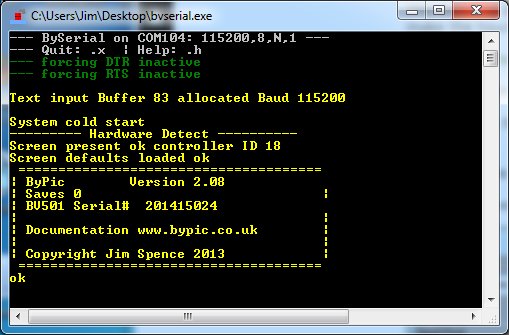
All being well this will be a similar screen to what you have. Note that Saves 0, which means that the flclear(0) worked okay. This means there is nothing saved in the PIC32 spare flash memory.
.tl This will invoke the dialog box shown below
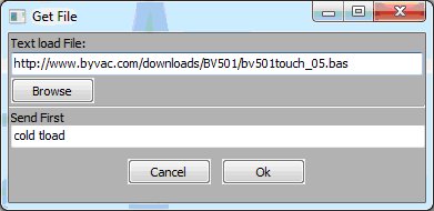
Copy and past the URL (in green above) into the dialog box as shown and then press Ok. The program will be downloaded from the internet into the BV501. If you have a slow or unreliable connection it may take a few attempts.
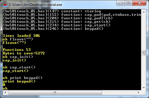
flsave("") This saves the bv501touch_05.bas program to flash
This is an essential part of the front panel and so it is easier to have this accessible at all times so it is easier to have it saved to flash. The program needs initialising before use, this is done by:
cap_init()
cap_start()
Now the main function keypad() can be used to retrieve the key codes of any key being pressed. This can be done interactively and so:
print keypad() This will return 0 when no keys are being touched.
If you do the same but touch a key before pressing enter it will return a key code value. Have a look at the demo program here for one way of how to use the BV501:
http://www.byvac.com/downloads/BV501/demo.bas [View file]
The above is the program that runs the demo.
ATFlash
On board is a serial flash device that is there to hold images and fonts. The size is 32Mb and is organised as 1000 x 4096 byte blocks (40k Bytes). There is a very simple filing system that BvSerial can utilise to store files onto the ATFlash.
To load a file onto the flash .upm <filename> is used. For example if there was an image in c:\temp\images\mying.bmp then the following would store that image onto the ATFlash:
.upm c:\temp\images\mying.bmp
The progress is shown by a series of dots. A directory can also be specified and any images (or fonts) in the entire directory will be saved onto the ATFlash. It is also possible to specify if a file is duplicated or deleted. This is purely controlled by the BvSerial program and for more information type:
.h upm
This will give the help information for the .upm command.
The files stored in the ATFlash are independent of the PIC32 flash, the contants can be seen by using the atlist command.
atlist()
This gives the block number, file name and size in blocks and bytes. The name is used for other commands such as showing an image or using a different font. The device comes pre-loaded with a few examples of images and fonts.
Images
BvSerial expects a bmp type file with 32 or 64k colours (24 bit). It will take the file and convert it to a suitable format before saving to the ATFlash. It is up to the user however to make sure that it will fit onto the available space. The maximum X is 128 pixels and Y is 160 pixels.
As an example use the atlist() command and disply a bmp file to the screen:
atlist() This will show that htere is a file called "up_100x100.bmp" if not use another bmp file
diimage("up_100x100.bmp",0,0)
The above command will display the image at co-ordinates 0,0. Fro more information on screen commands (those that begin with di) see www.bypic.co.uk/keywords.
Fonts
There are no built in fonts. The start up program looks for a font called "default.bff" in the ATFlash and uses that for the sign on screen. Fonts are created using CBFG.
CBFG web site (copy of CBFG can be found here)
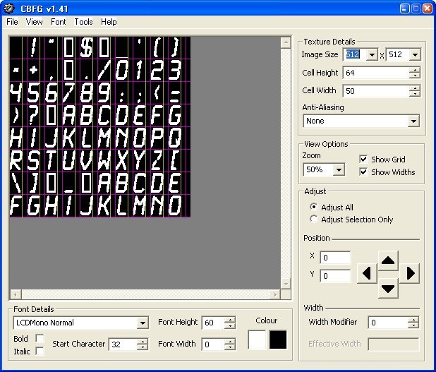
To create a user font, use the CBFG program and then save using the 24 bit Colour (RGB) option. This file can then be directly loaded into the ATFlash using the .upm option of BvSerial.
As an example of using fonts do the following:
difont("Impact50.bff") Assuming this is in ATFlash
dicls(0) Clears screen to black
ditext("AB")
The above will present a very large "AB" to the screen, if it dosent work then probably Impact50.bff is not on the ATFlash, you can check this by using the atlist() command. NOTE that it is case sensitive so "impact50.bff" is different from "Impact50.bff"
Demo Files
This zip file is a directory of all of the media files used in the demo. Unzip and and copy the files into a directory on the local drive called demoflash. Assuming the local drive is C then the files can be loaded directly into the AFflash by:
.upm c:\demoflash
This will take some time 15 minutes +
- http://www.byvac.com/downloads/BV501/demo.bas [View file]
- http://www.byvac.com/downloads/BV501/mediautils.bas [View file]
- http://www.byvac.com/downloads/BV501/bv501touch_05.bas [View file]
BvSerial
This is a program written in Python and so can be modified by the user. For this device it is particularly important as it is the method of getting media files (bmp and bff) onto the built in AT flash using the .upm command.
Some screens operate with RGB (red, green, blue) order and some with BGR. This is of no consequence in normal use as the firmware will always translate to RGB order. However when uploading media files it is the BvSerial program the determines the order. There is a file created by BvSerial "bvtermnn.cfg". This can be edited using notepad, the order entry should be set to either 0 or 1:
[rgb]
order = 1
If when saving images the colours look obviously wrong, then set the order to a different value, only order 0 or 1 will be accepted.
Images
|
|
 |
 |
 |