BV507 Home Control
Contents
- Hardware
- Firmware
- Oled
- Images
- Wifi
- Top Plate
- Circuit Diagram
- WiFi Getting started and troubleshooting


The BV507 is a ByPic controller with optional wifi, oled display and front plate. Ideal for home automation as the front plate will fit into a standard UK switch box.
Firmware
The firmware is included as an example of how to use the device. It is all written in user ByPic code and so can easily be changed.
Libraries
// #include "http://byvac.com/downloads/BV507/display.bas"
// #include "http://www.byvac.com/mBlib/flb/Library/2016/lib_wifi.bas"
// #include "http://byvac.com/downloads/BV507/touch_11.bas"
// #include "http://byvac.com/downloads/BV507/touch_13.bas" (*)
(*) This woks better but the other files will need modifying as the names are prefixed with cap.
Include any or all of the above depending on the functionality is needed, to get started here is a demo program:
http://byvac.com/downloads/BV507/bv507_demo.bas
Hardware
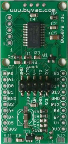

The basic unit consists of a PCB 28mm x 59mm with a PIC31MX170 running the ByPic operating system. On it's own it is a small powerful microcontroller with most of the spare ports free to use as required. There are 4 main connectors that are used in normal operation.
The serial and I2C connections are in the middle of the board and have surface mount pins (2.54 pitch spacing). The other connectors do not have any pins soldered to give the board maximum flexibility.
Serial
| Ground | Connection for ground |
| DTR | Connected to the processor reset |
| V+ | Connected to the 3.3V regulator (max voltage 6V) |
| TX | Serial output (RB10 UART2) |
| RX | Serial Input (RB11 UART2) |
I2C
For convenience, as the I2C bus is very useful for expansion this has its own connector and also has two pull up resistors so that any slave can be directly connected to it.
| 3V3 | Connected to the 3.3V power supply |
| SDA | I2C data line (RB9) |
| Ground | |
| SCL | I2C clock line (RB8) |
Expansion Port Pads
To the left and right of the board are the expansion port pads and are marked according to the PIC32 port they are connected to. If the front plate is not connected then all of the pins can be used for any purpose. If the front touch plate is needed than the top 4/5 pads on the left and right are used for this. See the top plate text later for details.
| JP3 | ALT | JP4 | ALT |
|---|---|---|---|
| RA0 | Keypad | RB3 | Keypad |
| RA1 | Keypad | RB15 | Keypad |
| RB0 | Keypad | RB14 | Keypad |
| RB1 | Keypad | RB13 | Keypad |
| GND | GND | ||
| RB2 | RB12 | ||
| RA4 | UART1 RX | RB6 | |
| RB4 | UART1 TX | RB7 | |
| RB5 | V+ | ||
| +3V3 | +3V3 |
Other pin use
- RA3 ESP8266 Reset
- RA2 ESP8266 CH_PD
- RB9 OLED and SDA I2C
- RB8 OLED and SCL I2C
- RB10 UART2
- RB11 UART2
WiFi
The wifi is a standard (but with ByVac firmware free) ESP8266 type that is soldered onto the PCB pads with the antenna protruding over the bottom edge of the board. The ESP8266 modules also vary but provided the TX/RX and power are in the same place then most should work. If you are providing your own wifi module than check the module with the annotated picture.
If using a ByVac module with the current firmware then the LED L1 will flash when the wifi is either not configured or cannot find the configured Access point. Details on how the wifi firmware works is here.
First Time
If the WiFi module if fitted then the factory settings default to an Access point, connecting to the access point will enable the WiFi to be configured. Full instructions are here.
WiFi UART Options

The board can be used in two basic ways a) (UART1) for communication with external media b) (UART2) to use it as a serial link to program the board.
UART1
When used for a) the wifi is used to communicate with other wifi devices. The board will hold the instructions and the wifi will act as a communicating device. For example to get the time of day from Google or to use some other web API that may be useful to the running program. When used in this way the wifi is connected to UART1 which is the serial port that is not used by the main ByPic communications.
The advantage of using this method is that it will create a reliable link with the outside world, it is also very easy to set up and program as a normal PC can be used for experimenting with.
UART2
UART2 is the main serial interface for ByPic and so connecting the wifi module to UART2 will enable the BV507 to be programmed over wifi. This can be extremely useful for applications where the BV507 is in situ, in a project that is not on the workbench. It is also possible with care to contact external sites such as Google or other websites.
Another advantage of this method is that a browser based IDE can be used.
The selection of UART1 or 2 is done by solder jumpers:
Solder for UART2
Solder for UART1
Wifi Programming
It is also possible to use this board to program the wifi. The interface is the same as the BV107 so see this link for some pointers of how to do it.
Reset (factory)
To reset the WiFi back to factory settings so that the settings web page appears again (see first time above). Remove the power, pull GPIO0 to ground and re apply the power for 6 seconds or until the flashing LED remains on.
The left hand end of R4 is a convenient place to do this, otherwise just use the pin on the WiFi.
OLED
The board is designed to optionally operate with a small oled display and an ESP8266 wifi; either one or the other or both. Because there are differing pin outs for some oled displays solder jumpers are provided.
 The oled display is the popular type that uses I2C for communication. However some of these boards have the ground and 3v3 swapped and so to cater for this solder jumpers are provided that must be 'made' before fitting the oled display.
The display is designed to fit on the back of the PCB facing forward and so once fitted there will be no access to the jumpers.

Above shows the orientation of the oled display. In this particular display the VCC(3.3V) is on the right hand side. The power to the OLED display is supplied through a MOSFET transistor so that it can be switched off to save power if required. Or the power switch can be used to instantly display or flash an item. This is controlled via PIC port RB5.
The OLED is programmed using ByPic and so the example provided can be changed to suit. As it stands there are three fonts and a capability of displaying images which have been pre-created using a paint program.
OLED Firmware
The drivers for the oled are written in ByPic and so can be changed by the user. There are two files associated with this the font.bas file and the display.bas file, both are as libraries above. The firmware provides a means of sending text to the oled and also images.
This follows the same technique as for other 128x68 ByVac devices. For this device the method is to convert the image file to a .bas file and save this to flash before use. There is a demo image in the font library that can be displayed by:
ol_init()
ol_cls()
ol_img(0,0,*demo_img())
There is a utility to create .bas files from a bmp explained here. Choose the ByPic output option, output type decimal or hex will work equally well.
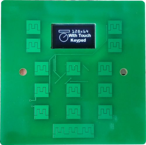
Front Plate


The front plate is 86mm x 86mm and is designed to fit into a standard UK switch box. The holes will also match the standard screw fixings.
 This is the kind of box that the plate will fit. The touch pads will work through 2mm acrylic or simply through photo paper and so any design can be used to suit the application. Not all of the pads need to be used of course.

Here is an overlay for example that was created in Inkscape. This can be printed out on sticky backed photo paper and for extra protection the whole plate can be covered with acrylic.
The BV507 is permanently attached to the front plate using either 2, 4 way SIL SMD pins or 1, 5 way and 1, 4 way the latter arrangement leaves a ground pad free for other purposes.

The above shows the pins that are attached to the front plate. although it is possible to attached all the pins to the front plate as there are sufficient pads on the front plate only these pins are required to make all of the touch pads work. The other pads can have pins pointing outwards so they can be attached for general purpose use.
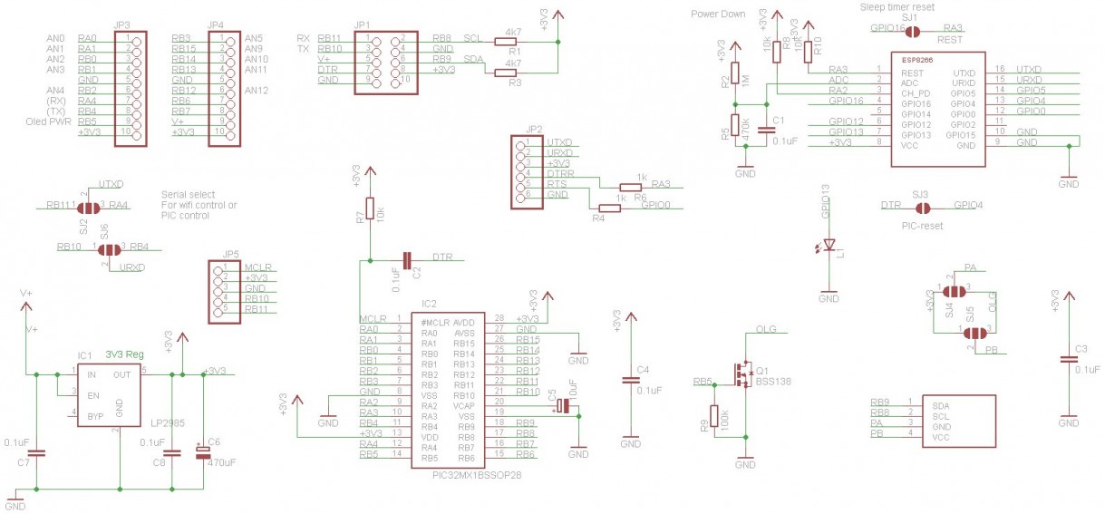
Circuit Diagram
WiFi - Getting started
This assumes that the ESP8266 module is attached to the BV507.
UART: By default (i.e as supplied) the wifi is connected to UART 1 via the jumpers on the back of the board, see the image above.
The wifi library should be included of course
LED: The led will indicate the condition of the wifi as follows:
- Led off: Normal operation
- Led on (dim): Not enough power to operate the wifi, the device will not work if the led is continuously illuminated.
- Led Flashes and then goes off: Normal operation
- Led continues to flash: wifi not configured
If the LED is dimly lit this means that there is not enough power to operate the wifi, there is a considerable current requirement a few milliseconds at start up. Sometimes disconnecting and then reconnecting will cure this as the reservoir capacitor will be charged up. If the LED is flashing then the wifi cannot connect to the access point, this could be because the access point is no longer available or out of range or the SSID and password are incorrect. Also possibly the wifi is set to AP rather than station.
Functions: See the library instructions.