BV508_V2
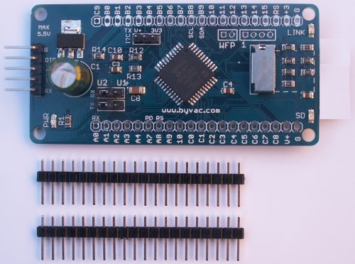
This is a small self contained microcontroller board with an on board operating system; ByPic that can be programmed using the serial interface and just a simple text file.
The pins are on a 0.1” (2.45mm) pitch and so can be plugged into a breadboard or a standard strip board.
The board si designed for use with an WiFi (ESP8266) radio or a 433MhZ HC-12 type radio each of which can be directed to UART1 or 2. The power supply is capable of supplying the TX burst current.
Features
- SD Card holder for up to 32GB
- Pads for WiFi (ESP8266-12E) // can be supplied with or without
- Pads for HC-12 type serial radio transceiver - lower power needed
- ByPic installed
- 35 I/O - some used for WIFi and SD card
- PIC32 MX170 running at 40MHz
- Usual timers, I2C, SPI, PWM, touch etc.
- 64k RAM
- 256k Flash
**NOTE: It comes with the pins but not attached so that the user can use it either way round.
Size: 34mm x 70mm
Qiuck Start
- Down load BVSerial (the IDE) as described here.
- Connect the BV508_V2 to a USB to serial device and establish communication. Further details are here if this proves difficult. Serial connection details are in the text below.
There should be a prompt similar to this.

Type .edit (dot edit) and the editor will open ready to go. Further information on using ByPic can be found where the above IDE was obtained from (http://www.bypic.co.uk/index.php/IDE).
WiFi
If the device is fitted with wifi the best way of setting this up as a station is to use ByPic, although it can be done with a web interface with intermittent results.
1) Set jumper [3] to UART 1, that is the middle and right hand side pins marked U1
2) Copy and paste the following into the editor:
// #include "http://www.byvac.com/mBlib/flb/Library/2016/lib_wifi.bas"
constant SSID$ "my ssid"
constant PASS$ "my pass"
function go()
wifi.start(*BV5082(),1) // refers to the com port used for commms
wifi.setstation(SSID$,PASS$)
endf
function test()
wifi.dt$()
endf
Change "my ssid" and "my pass" to match your network
3) Press F4 to load into the BV508. Make sure there are no errors, if so correct and press F4 again.
4) in the terminal window type go() to run the function go(). This should return with 'Sucess'ok if not then check your SSID and password, also check that you are not too far away from the router, although the ESP8266 has excellent range.
5) If 5) is okay then type test() and the current time should be returned.
All being well you are now connected to your home router, the settings are persistant and will be available through power cycles.
There are other useful functions in the wifi library that can now be explored.
Hardware

[1] Serial interface default 115200 Baud
[2] 1A Regulator and large reservoir capacitor for wifi TX
[3] Wifi Radio serial selector
[4] I2C pull up voltage selector
[5] PIC32 CPU
[6] WiFi re-programming
[7] SD Card holder
[8] GPIO interface
Serial
The serial is connected to UART2 which is the main interface used for programming and general use. The UART pins are 5V tolerant and the default Baud rate is 115200.
| Pin Name | Function |
|---|---|
| G | Ground |
| DTR | Connected to the reset, a pulse on this pin will reset the PIC |
| +V | Main power input Maximum input voltage is 18V |
| TX | Output from PIC UART 2 (RB10) |
| RX | Input to PIC UART2 (RB11) |
Regulator
This is a 1A regulator which supplied the 3.3V required for the PIC32 and the WiFi. It needs to be reasonably large to accommodate the TX surge that occurs on the ESP8266 transmit and start up. This is also helped by a large capacitor.
Because of the small on board heatsink the regulator will not be able to handle a continuous 1A.
The minimum voltage should be about 4.5V as this will allow sufficient voltage drop to give 3.3V. The maximum input voltage is 18V.
Serial Selector

This selector directed the TX/RX from the wifi(radio) to either UART1 or UART2. UART2 is the main default input as used on the serial connector and UART1 is a spare.
UART2 would be used for programming and using the device just as if it were connected to the serial port as above. It could be considered as a USB to Serial connector with a very long lead.
UART1 would be used to have the WiFi or radio do more control applications such as telemetry logging or perhaps make the device into a web server.
The pins used for this are:
TX RA0
RX RB2
I2C Voltage Selector
The device has on board pull up resistors for the I2C bus. These can be set to pull up to the supply voltage or to the 3.3V regulator voltage. This will depend on the voltage requirements of the slave device.
SDA RB9
SCL RB8
There is no connector specifically for I2C. The lines are on the general GPIO pads.
PIC32
The board is based on a PIC32MX170F256D that has 256k Flash, 64k RAM and operates at 40MHz.
A full list of features is here on the data sheet
A proportion of the flash is taken with the ByPic operating system. However there is still sufficient room for complex programs. The actual spare flash is approximately 133k which is good enough for several thousand lines of code.
Some other features of this processor are:
- 40MHz clock rate
- 20uA low current mode (may not be achievable on this device)
- Audio features
- ADC 10 bit
- Charge Time Measurement Unit
- Comparators
- Timers (5)
- SPI, I2C, UART x 2
- Some pins are 5V tolerant
WiFi Re-programming
If supplied the WiFi module is programmed with the ByPic transparent bridge, however if in situ the Wii can be re-programmed using these pins.


- Disconnect the power
- Short out the pads marked WP
- Connect the USB to Serial as shown and follow these instructions
NOTE: the V pin on the connector as shown is not connected to anything on PCB version b so just power up in the normal way.
Radio
WiFi Installation

Normally the device will be purchased with the WiFi in place, however it takes a standard ESP8266-12E with the following pin outs.

GPIO is also used for the power down and reset pins.
433MHz radio

The pads are laid out for a HC-12 type module. This is a Si4663 with an on board microcontroller. The device behaves as a simple serial link and so can also be used as a 'long' serial lead or be used for telemetry.
The set pin which can be taken low allows the device to be re-configured for other Baud rates and modes. In theory this device should be capable of greater radio range then WiFi and it does consume considerably less current.
GPIO Interface
This chip has a Peripheral Pin Select (PPS) device and so most of the pins used could be changed. The pin functions described in the table are those used by the ByPic firmware.
The physical layout of the pads are on a 0.1 grid and so will fit on standard stripboard if required.
| Pin | Used | Notes |
|---|---|---|
| A0 | YES | Used for UART1 TX |
| A1 | ||
| A2 | ||
| A3 | ||
| A4 | ||
| A7 | YES | Connected to WiFi power down CH_PD, when high WiFi is enabled |
| A8 | YES | Connected to WiFi reset |
| A9 | ||
| A10 | YES | SD_CARD Chip select |
| C0 | ||
| C1 | ||
| C2 | ||
| C3 | ||
| C4 | ||
| C5 | ||
| C8 | ||
| C7 | ||
| C8 | ||
| V+ | Connected to V+ on serial interface and so would normally be the supply voltage | |
| G | Ground |
Row 1 5V tolerant pins
| Pin | Used | Notes |
|---|---|---|
| C9 | ||
| B0 | ||
| B1 | ||
| B2 | YES | Used for UART1 RX |
| B3 | ||
| B4 | ||
| B5 | YES | SD_Card MOSI (can also be used for other SPI) |
| B6 | YES | SD_Card MISO (can also be used for other SPI) |
| B7 | ||
| B8 | ||
| B9 | ||
| B10 | YES | UART2 TX This is also connected to TX on the serial connector and the selector jumper |
| B11 | YES | UART2 RX This is also connected to RX on the serial connector and the selector jumper |
| B12 | YES | Connected to the SET pin on the HC12 Radio module |
| B13 | ||
| B14 | ||
| B15 | YES | SD_CARD Clock (can also be used for other SPI) |
| RS | Connected to the MCLR (reset) pin of the PIC32 | |
| +3 | Connected to the output of the 3.3V regulator | |
| G | Ground |
Row 2 5V tolerant pins
The pins shown marked YES in some cases can also be used for other things, for example if the WiFi is not used then all of those pins are available.I2C Interface
The I2C interface can either be a slave or master. It has built in 4.7k pull up resistors and is wholly controlled by software. A library is available for either master or slave. To use this interface the software needs to be installed first via the serial interface.
SCL: B8
SDA: B9
The processor is a PIC32MX170, this has 256K flash and 64K ram.
Circuit Diagram

Click image to enlarge
Programming
The device has installed ByPic. This is permanently in flash and makes programming much easier. No programmer is required simply download the code using a serial connection, the code is written in text, this includes the libraries and so can be modified by the user as required.
To get started connecting the device to a serial port and using the ByPic language follow this link.
Programming with a PICKit
The device can be programmed in C using a PICKit but be warned that the boot loader will be overwritten and you will not be able to use ByPic anymore via the boot loader.

History
November 2014 BV508 (original) PCB Version - 0
September 2015 BV508 (original) PCB Version a - added TX and RX jumpers
January 2017 BV508_V2 PCB Version_b