BV509
**There is a new version of the BV509 (BV508_2) to be released April 2016, this will be similar (SD card, wifi) but based on the MX170 **
 This is a small self contained microcontroller board with an on board operating system; ByPic that can be programmed using the serial interface and just a simple text file.
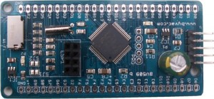
The pins are on a 0.1” (2.45mm) pitch and so can be plugged into a breadboard or a standard strip board.
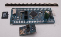
The board comes with a socket for connecting to an ESP8266 Wi-Fi module and with firmware for driving that module making it easy to build server or client applications.
**NOTE: It comes with the pins but not attached so that the user can use it either way round.
Size: 35mm x 70mm
The ByPic operating system will read and write to an SD card using either FAT16 or FAT32 and so is compatible with Windows and Linux.
There are TWO microcontrollers on this board, a PIC32MX370 with 512K Flash and 128k RAM running at 80MHz and an ESP8266 wi-fi controller. This is on a separate board with its own antenna
There are various options from just the BV509 to the BV509 with SD Card and ESP8266. The downloadable firmware requires that the ESP8266 uses 00170901 or similar.
A special feature of this device is that the ESP8266 and SD card can be powered down separately and thus ony about 700uA is used on standby.
Resources
 ByPic Language Guide and documentation
- Purchase <Byvac Shop> <eBay shop>
- PICMX370 Family data sheet
- ESP8266 Library
- Wi-Fi kit tutorial uses the BV508
Rookie2 zip file. Unzip this file onto an SD card, put in the BV509 and then reset using .r (dot r). It will load rookie3 and the ESP8266 library
Hardware
The board is based on a PIC32MX370512H that has 512k Flash, 128k RAM and operates at 80MHz. There is also a lower cost board that uses the PIC32MX340H that has 512K Flash,and 32K RAM
All of the pins are brought out to the PCB and are marked. There is a low power 32kHz crystal on board allowing the real time clock features to be used.
Features
- Separate power supply for ESP8266 and SD Card so they can be switched off
- Real Time clock
- SD Card up to 32Gb, FAT16 and FAT32
- Low power sleep mode 700uA
- MX340 Option 512K Flash, 32K RAM
- MX370 Option 512K Flash 128K RAM
- 80MhZ
- 5V tolerant pins, most can be re-mapped
- Approximately 54 GPIO
- Up to 27 ADC Channels
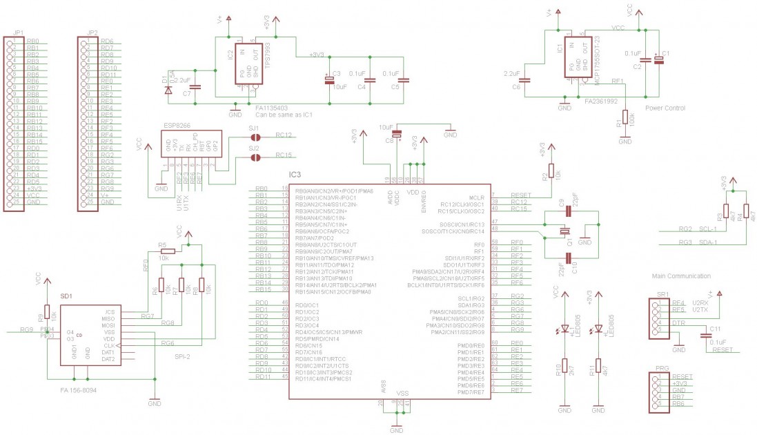
Circuit Diagram - Click to enlarge
Power Down
This feature may change in the future as the hardware currently uses two regulators that may not be necessary.
The power down feature works by switching off the second regulator, this regulator supplies power to the SD card and the ESP8266 and so they are rendered completely inoperative and thus consume zero power. In this way and also using the PIC sleep mode the power consumption can be reduced to about 700uA
http:\\www.byvac.com/downloads/ByPic/BV509_powerWF.bas
The above module that is also supplied on the zip file will power down the BV509 for periods of 16 seconds. This is the time set by the watch dog timer. To completely power down, some ports need to be set to either input or output, see the code so understand how this works.
The main function is called powerControl(time) and so powerControl(5) will shut the BV509 down for approximately 80 seconds.
Connectors
NOTE: This (MX370 not MX340) chip has a Peripheral Pin Select (PPS) device and so most of the pins used below could be changed. The pin functions described in the tables below are those used by the ByPic firmware or rookie which is added to the firmware.
Serial
| Pin Name | Function |
|---|---|
| G | Ground |
| DTR | Connected to the reset, a pulse on this pin will reset the PIC |
| +V | Main power input Maximum input voltage is 18V |
| TX | Output from PIC UART 2 (RF5) |
| RX | Input to PIC UART2 (RF4) |
The on board regulator can handle up to 300mA. The ESP8266 consumes an average of about 100mA peaking to 200 to 200mA so it is well withing the regulators range. The minimum voltage should be 4.9V* as this will allow sufficient voltage drop to give 3.3V
* The device will not function correctly with a poor power supply, ir will work on slightly less then 5V but 5V is recommended, the regulators can handle up to 6V. Some USB ports do not output the full 5V.
The default Baud rate is 115200 with 8 data bits and no parity. The UART pins used are 5V tolerant so it can be used with either a 5V or 3.3V USB to Serial device.
ESP8266
| Pin Name | Function |
|---|---|
| TX | Output, connected to PIC UART1 RX (RF2) |
| GND | Ground |
| CH_PD | Power down pin, high for power up connected to PIC (RE6) |
| GPIO2 | Connected to solder pad and then to (RC12) |
| RST | Reset connected to (RE7) |
| GPIO0 | Connected to solder pad and then to (RC15) |
| VCC | 3.3V from regulator (2) |
| RX | Input, connected to PIC UART1 TX (RF3) |
By default GPIO0 and 2 just go to the solder pads that are left unconnected. If this pins are required the solder pads can be shorted to connect the the PIC pins as in the above table. The pins used are marked on the PCB.
SD Card
| Pin Name | Function |
|---|---|
| Detect | Goes low when a card is inserted (RG9) |
| GND | Ground |
| VCC | Power from regulator 2, P2 |
| CS | Chip select (RF0) |
| MISO | Output from SD Card (RG7) [SPI] |
| MOSI | Input to SD Card (RG8) [SPI] |
| CLK | SPI Clock (RG6) |
GPIO
All of the GPIO pins are brought out to the side connectors, these are laid out at 0.1" grid and so will mate to any standard breadboard etc. The pins are marked on the PCB and so the table will show only those pins that are not obvious.
| Pin Name | Function |
|---|---|
| V+ | This is the input voltage and is connected directly to the input side of the regulator |
| RS | Connected directly to the MCLR pin of the PIC |
| P1 | Output from regulator 1 @ 3.3V |
| P2 | Output from regulator 2 @ 3.3V. This can be switched on or off using GPIO (RF1). When RF1 is low the regulator will switch off. |
| G | Ground |
Some pins are duplicated, for example RB10 (UART2 TX) and RB11 (UART2 RX) appear on the side connector and also on the serial connector so take care when deciding which pin to use. As a reminder the pins used for these and other functions are marked on the PCB.
I2C Interface
There is not really a specific connector for the I2C interface, however there are two pull up resistors connected to RG2 and 3 so these can be mapped to the I2C using PPS.
SCL: RG2
SDA: RG3
Power
A feature of this device is that the second 3.3V regulated power also has a 1000uF capacitor to act as a 'reservoir'. This is because the ESP8266 can peek largish currents and it has been found that such a capacitor is in fact needed.
Programming
The device has installed ByPic. This is permanently in flash and makes programming much easier. No programmer is required simply download the code using a serial connection, the code is written in text, this includes the libraries and so can be modified by the user as required.
To get started connecting the device to a serial port and using the ByPic language follow this link.
Programming with a PICKit
The device can be programmed in C using a PICKit but be warned that the boot loader will be overwritten and you will not be able to use ByPic anymore via the boot loader.
There are 5 pads near the PIC that correspond 1:1 with a PICkit, the square pad is pin 1, it is marked on the PICkit with a white triangle.
History
Released February 2015.
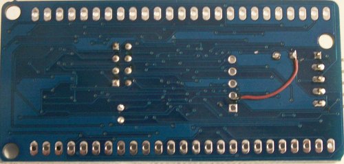
pcb: bv509-b 27 Feb 2015
The current version has a minor PCB track error which as been fixed and in no way detracts from the performance of the board.