BV502_V2_plus

The BV502_V2_plus
This is a small self contained microcontroller board with an on board operating system; ByPic that can be programmed using the serial interface and just a simple text file.
The pins are not attached to give the board more flexibility. But for experimentation and the like it is useful to attach them upwards so that standard DuPont connectors can be used.

Size: 60mm x 27mm
Serial Driver
The board uses the CH340G USB to Com port serial chip. The driver for this chip will automatically be installed by Windows and give a COM port number. If this is the case ship this section.
Sometimes the driver may not automatically install on Windows, in which case windows will report the problem or you will simply not get a usable COM Port.

Here for example in the device manager, I have used a modified device which also uses the CH30G (Rams is a 3d printer board) and the driver is not compatible with the CH340G in the BV502 and so no COM port is available.
The screen shot is shown with the BV502 plugged in. To solve the problem keep the BV502 plugged in and right click on the "RAMPS in my case 2) and uninstall the driver.
After uninstall, give it a few seconds and the correct driver will be automatically installed by Windows, thus:

Drivers
Use these as a last resort as the driver will load automatically given the right conditions:
Hardware
The board is based on a PIC32MX170F256D that has 256k Flash, 64k RAM and operates at 40MHz.
There are 4 connector rows conveniently laid out each serving mainly on port
| Row 1 | Row 2 | Row 3 | Row 4 |
| A0 | C0 | B0 | 3V3 (I2C) |
| A1 | C1 | B1 | B9 (SDA) |
| A2 | C2 | B2 | G (I2C) |
| A3 | C3 | B3 | B8 (SCL) |
| A4 | C4 | B4 | B10 (TX) |
| A7 | C5 | B5 | B11 (RX) |
| A8 | C6 | B6 | B12 |
| A9 | C7 | B7 | B13 |
| A10 | C8 | 3V3 | B14 |
| v+ | C9 | GND | B15 |
Notes
- PIN These pins are 5 volt tolerant
- V+ is the 5V output from the USB device. It can also be used to power the device whrn the USB is not in use.
- The I2C interface has 4k7 pull up resistors attached to the 3v3 line
- 3v3 is the out put from the USB device
- TX/RX are connected to the USB device
- All pins are free for any use except the TX and RX
The 3v3 is derived from the CH340G USB device and has limited current capabilities.
Serial Interface
The serial interface is provided by a CH340G USB serial port. The default Baud rate is 115200. Windows has built in drivers for this device but if not they can be easily found.
Successfully attaching to the USB will give the 'ok' prompt.
PIC32
The processor is a PIC32MX170F256D, this has 256K flash and 64K ram. A proportion of the flash is taken with the ByPic operating system. However there is still sufficient room for complex programs. The actual spare flash is approximately 133k which is good enough for several thousand lines of code.
Some other features of this processor are:
- 40MHz clock rate
- 20uA low current mode (may not be achievable on this device)
- Audio features
- ADC 10 bit
- Charge Time Measurement Unit
- Comparators
- Timers (5)
- SPI, I2C, UART x 2
- Some pins are 5V tolerant
Circuit Diagram
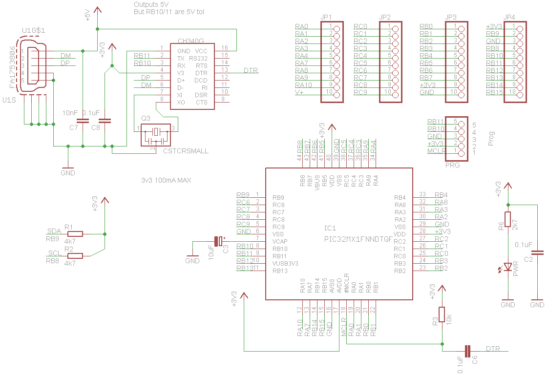
Click image to enlarge.
SD Card
To use an SD card with this device do the following.
1) Replace the normal firmware with the SD Card firmware here

See that the log in screen is different as it attempts to mount the SD card. There is no consequence of not having a card at this stage.
2) Wire up an SD card using a suitable holder using the following wiring
| PORT | Description | SD Card |
| RB15 | Clock | CLK (SCK) |
| RB6 | MISO | DO (MISO) |
| RB5 | MOSI | DI (MOSI) |
| RB14 | CS | CS (SDCS) |
| V+ | To SD Card with regulator |
** NOTE: The 3v3 supply on this board does not have sufficient currant to drive an SD Card, most SD Card boards now have built in regulators.


3) Insert an SD card, reset and you will now see that the firmware will show a 0:/ ok prompt, this means that the SD is in place. NOTE the prompt will only show if there is an actual formatted SD card in place.

If you get error(14) See troubleshooting.
Programming
ByPic
The device has installed ByPic. This is permanently in flash and makes programming much easier. No programmer is required simply download the code using a serial connection, the code is written in text, this includes the libraries and so can be modified by the user as required.
To get started connecting the device to a serial port and using the ByPic language follow this link.
Using PICkit
WARNING Using a PICKit will overwrite the boot loader so ByPic cannot be installed. The only way to re-install ByPic would be to get another BV502.
The IC can also be programmed using a PICkit simply by offering up the device to 5 pins that have been arranged for that purpose.

The above is the pin connections for a standard PICkit. At the time of writing there is no PICKit 2 firmware available that will program the MX170 so a PICKit 3 must be used via MPLAB.
History
- February 2017 release of V2 Plus (should really be called V3)