BV504
 This is a PIC32MX170 microcontroller that has a permanently attached user interface in the form of a 14 input touch pad and 16x2 lcd display.
The processor which has 24 GPIO for custom use is a PIC32MX170F256D that has 256K Flash and 64K RAM. It comes with a built in operating system (ByPic) for Rapid Application Development.
This is ideal for a front panel to any project. It will also fit into a standard project box E76, see
http://www.ebay.co.uk/itm/PLASTIC-BOX-ENCLOSURE-CASE-HOBBY-ELECTRONIC-PROJECT-ABS-E76-/130738084288)
It can be battery powered as it has a built in 3.3V regulator and has a very low profile.

Including the pins it is about 11mm deep.
The zip file contains an SVG layout and the accurate DXF so that custom overlays can be produced.
Firmware
The device comes loaded with ByPic via a boot loader and this can be updated from the firmware site.
In addition to this there are the LCD and Touch drivers that are loaded on top of this, the script file for doing that is here.
http://www.byvac.com/mBlib/flb/Library/Devices/BV504/BV504.script
The IDE is needed for loading a script and details of how to load a script are here.
Hardware
The device uses a PIC32MX170F256D which has 256K flash and 64K ram. some of the pins are used for the touch interface and some for the LCD display
Pins used for the device, none of the pins in this table are brought out to the user connector.
| Pin | Use |
| RB10 | UART2 TX, Main communication |
| RB11 | UART2 RX, Main communication |
| RB8 | LCD I2C SCL [1] |
| RB9 | LCD I2C SDA [1] |
| RC3 | LCD reset |
| RC0 | Touch pad R1 |
| RC1 | Touch pad R2 |
| RC2 | Touch pad R3 |
| RB15 | Touch pad R4 |
| RB3 | Touch pad C1 |
| RB12 | Touch pad C2 |
| RB13 | Touch pad C3 |
| RB14 | Touch pad C4 |
NOTES:
[1] This can also be used for user I2C providing a different address is used, the LCD address is 0x7c (0x38 7 bit)
Connectors
NOTE: This chip has a Peripheral Pin Select (PPS) device and so most of the pins used below could be changed. The pin functions described in the tables below are those used by the ByPic firmware or rookie which is added to the firmware.
Serial
| Pin Name | Function |
|---|---|
| G | Ground |
| DTR | Connected to the reset, a pulse on this pin will reset the PIC |
| +V | Main power input Maximum input voltage is 18V |
| TX | Output from PIC UART 2 (RB10) |
| RX | Input to PIC UART2 (RB11) |
WiFi
This can be added instead of the USB to serial converter, the IDE can then be a web application.
Wifi to Serial adapter

I2C Interface
The I2C interface has built in 4.7k pull up resistors and is wholly controlled by software.
SCL: B8
SDA: B9
GPIO
There are 21 GPIO pins for general use, these are clearly marked on the PCB. The following pins are 5V tolerant:
RB7, RB6, RB5
RC5, RC6, RC7, RC8, RC9
RA9, RA8, RA7, RA10
PIC32
The processor is a PIC32MX170, this has 256K flash and 64K ram. A proportion of the flash is taken with the ByPic operating system. However there is still sufficient room for complex programs. The actual spare flash is approximately 133k which is good enough for several thousand lines of code.
Some other features of this processor are:
- 40MHz clock rate
- 20uA low current mode (may not be achievable on this device)
- Audio features
- ADC 10 bit
- Charge Time Measurement Unit
- Comparators
- Timers (5)
- SPI, I2C, UART x 2
Circuit Diagram
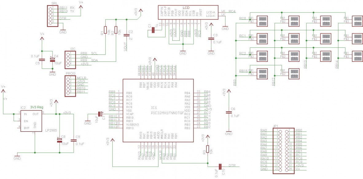
Click to enlarge
SD Card
To use an SD card with this device do the following.
1) Replace the normal firmware with the SD Card firmware here
2) Wire up an SD card using a suitable holder using the following wiring
| Chip Pin | PORT | Description | SD Card |
| 26 | RB15 | Clock | CLK |
| 15 | RB6 | MISO | DO |
| 14 | RB5 | MOSI | DI |
| 25 | RB14 | CS | CS |
** Don't forget the SD Card requires 3.3V
3) You should now see that the firmware will show a 0:/ ok prompt, this means that the SD is in place. NOTE the prompt will only show if there is an actual formatted SD card in place.
History
Released Feb 2015 (PCB marked BV501_V2-b